Process and Production: Sub-Object Modelling with Jay Payne
Sub-Object Modelling
For today's workshop session with Jay, we will be creating our own 3d character model out of a singular shape with the use of various tools such as extrude and tools that can be found on the sub object tool bar. We will also be looking at cel shading these character models nearer to the end of the workshop session. I am eager to get on with this workshop because this will be my first ever 3D character model creation.
Jay showed us Pictoplasma, an organisation that is dedicated to the art of character design, the site has an awesome archive of character designs that have been submitted by the general public and after having a quick flick through I would love to submit my Nythim character to the 'Pictofolio' they actually have a themed submission on at the moment called 'character stare down' where you can submit a character gif of the character staring towards the viewer this would be a great addition to my character and I might consider having a look at creating a simple loop GIF to upload. Below is a link to Pictoplasma and the Pictofolio.
To get started, the core shape that we will be editing will be the standard cube, once created I changed the XYZ attributes to 400X/100Y/200Z with segments set at 2/1/1. After I activated Gouraud shading (lines) which can be found in the viewport menu to help me see the segments of the shape.
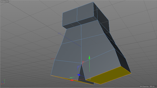
Next I made the shape editable and rotated the camera to see the underside of the shape, with the point selection button found on the sub-object toolbar I can select the two centre points of the lower section of the shape. With these two points selected I can drag the points down by approximately 50cm.
Next I selected the poly selection button which can also be found in the sub-object toolbar, this allows me to select entire panels of the shape in comparison to the point selection option. once selected I rotated the camera to see the top of the shape, right clicked and selected the extrude tool. I then extruded the top part of the shape by 100cm to further extend the shape. This will become the body of the character.
After extruding the top of the box I reselected the point selection button and rotated the camera to the front of the shape, additionally I selected the rectangle selection tool which can be found by clicking and holding the live selection button. next I unticked the 'only select visible elements' option so I would be able to select points on the opposite side of the shape without having to rotate the camera view continuously, this came in handy for the next part. with the rectangle selection tool active I created a selection around the top 2 levels of the shapes and using the scale button I tapered the box top inward by approximately 75% with the red arrow.
After tapering the top 2 levels of the shape I selected the very top level and repeated the tapering process again to try and get an even taper throughout the shape, however I think I got my approximations a little out because it didn't result in a completely even taper, this is not an issue however I didn't want to spend too long trying to make the taper on both levels perfect.
Once the shape had been tapered I selected the top two faces of the box using the poly select tool and extruded it by a further 100cm, I then selected the front faces and extruded it by 50 cm forming the head and face of the character.
Afterwards it was time to create some legs for the character, I rotated the view to the bottom of the character and selected the bottom two faces, I selected extrude option and unticked preserve groups. what this does is creates a separation between the two panels allowing me to make two separate extrusions an example can be seen below as I created the legs by extruding the selected faces by 100cm
With the live and point selection tools active, I selected the inner points of the bottom of the legs and raised them by 50cm to create a flat surface. Once flat I then individually dragged the bottom of each leg inwards by 10cm to reduce the size of the gap between the legs. afterwards I extruded the bottom of each leg by a further 50cm to elongate them. once extruded I selected the front new front faces at the bottom of the legs and extruded them 50cms to form the toes of the character model.
With the legs created I next moved onto creating some arms for the character model. With the central side faces selected, I right clicked and set an inner extrude at 30cm creating smaller panels within them. Next i selected the rear points of the inner extrusions and moved them forward by 15cm to create a thinner more square shaped panel to extrude out from.
To create the arms I started with the shoulders by extruding the inner side faces out by 65cm and then angled them forward by 40cm, afterwards I individually rotated both arm ends forward by approximately 30 degrees so the arms face forward. once angled I then extruded both arm ends by 60cm followed by individually scaling them by 150%, doing so will create the base of the hands that were then extruded another 50cm.
With the hands complete, I have a base character model that I can work with for the rest of this workshop. I can now select the model button found on the left side of the UI and rename the cube in the layers tab to 'BodyMesh'.
The next step is to add a HyperNURBS or 'Subdivision Surface' which is a method of creating a smooth object mesh in 3d modelling. Adding a subdivision surface to the project and dragging the body mesh into the subdivision surface on the list resulting in the screenshot below.
To adjust the shape of the character I must first turn off the subdivision surface in the object list menu, this will return to the body mesh to the blocky low poly shape from before. I had a little bit of time to play around with the shape of the head and face using the selection tools and the Inner Extrude tool.
To give the character some eyes I selected both face panels with the poly selection tool and used the inner extrude with preserve groups option unticked set with the offset of 55. when editing the face of the character I went for a very spiky angular facial structure and included nostrils by using the inner extrude again on the lower half of the face.
Once I was done editing the face I next created set selections to assign to different materials, the set selections in particular were the body itself, the eyes, the bottoms of the feet, the end of the arms and the face.
LOOK AT IT! WHAT IS THAT FACE! reminds me of the crappier cousin to the Demogorgan from Stranger Things.
During the break in the workshop I decided to rework the face for the Character model, I made a more curved head and even created an opened mouth with a tongue and two tusk like teeth. I also changed the set selections to the tongue and teeth instead of the end of the hands and feet.
I wanted to create a character that was inspired by an orc, so green and butt ugly. I made the material for the teeth an off white and the material for the tongue a pinkish red.
Here is an example of a cube with theses settings activated.
Note that the Sketch & Toon system is similar to cel shading but a more complex, much slower to render and is more time consuming to set up in comparison.
To create cel shaded material I selected a material, activated luminance, texture, cel and added three colours of my choosing, seeing that I am creating an orc character I chose to have different shades of green and did a test render, however it came out quite blue green so I spent. a bit of time tweaking the colours to my liking.
Once I had finished adjusting the colours set for cel shading I added a floor, background, lights, added some shadow options and test rendered. It came out really well in the end, I do admit I got a little bit lost with the cel shading part but I was able to make it in the end.
Below is the final render for this workshop I set the floor and background colours as my standard black and white (e6e6e6 for white and a1a1a1 for black)
Additionally I added a null object with a camera that rotates around the character and created a short 8 second video which you can see below via Vimeo. One thing I did notice and didn't even take into consideration was that the character's back is flatter than an ironing board, so I intend on editing that in my spare time along side perhaps repositioning the arms and legs a bit.
After the workshop I went back to the character design and added some eyes using the tools from today's workshop. This workshop was rather a enjoyable session and this was my first ever 3D character model, I think the outcome of this workshop went rather well and I am eager to experiment with 3d character modelling in the future.
Post Workshop Development.
Since the workshop of sub object modelling I have experimented with Cinema4D in my spare time, thanks to the help of this workshop in particular I was able to make my first own made model of a pair of headphones for my Genealogies project. The screenshot below is a quick render of the headphones with a polystyrene texture applied to it.
You can find the creation and development of this 3D model with the following link.
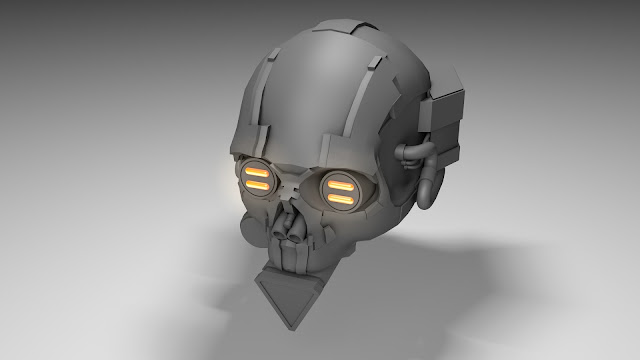
I further experimented with sub object modelling in a personal project nearer to the end of the uni year. With the help of tutorials and everything I had learnt in the workshops with Jay, I created my very own skull 3d model and added various shapes and designs to form a Cyberpunk Inspired Industrial pyro-themed skull that has metal plate extruding from the bone and wires/pipes implanted and wrapping around the skull and even a canister lodged where the jaw should be, below is a render I created of this piece, I chose to not create a detailed texture for this render but instead keep most of the model grey and apply various effects to make the model stand out. this piece was inspired by a variety of pieces as well as the video game of DOOM.


Comments
Post a Comment